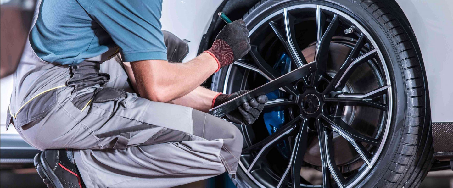
Road
Force Procedure:
This procedure was
designed and used by
me in my day to day
business, in dealing
with the troublesome
task of finding
those road force
problems that no one
else can fix. After
many months of
getting nowhere with
information from the
manufacturer I assembled
this information
with factual
information that I
proved or disproved
to myself. Now
after two years of
day to day usage I
am willing to share
this pain staking
information with
you. First thing,
this procedure is
not a replacement
for information for
manufacture's
recommendations, and
is not intended to
be so. It is my
professional and
personal opinion,
this procedure works
for me with no bias.
With that said lets
begin; First thing,
the tire must be
inflated to maximum
tire pressure, check
the side wall of the
tire for
your safety. This
is done for two
reasons, first is to
make the tire as
round as possible,
second is to
exaggerate the tire
or tires that have
the greatest problem
during the
procedure. Tires
with more air
pressure have a
higher road force in
pounds. Second thing
you must drive the
car for a minimum of
5 to 10 miles to
ensure the tire gets
to a warm
temperature.
Remember in Florida
the roads are always
hot, you may need to
drive a little
further. Third the
car must be brought
in to your shop and
put in the air on a
car rack or lift
with the tires off
the ground. Leave
the car sit for a
minimum of 15 to 20
minimum. Believe me
guys, if you don't
do these three steps
your wasting your
time. I know all
to well how much
time I wasted. All
this is done for
good reason, the GSP
9700 machine is a
great machine if you
use it properly.
But the fact is,
it's some times too
good, the machine
doesn't know the
difference between
road force, parking
lot memory, [that is
the spot on the tire
that is in touch
with the ground that
is as hot as the
asphalt it's
touching] or a flat
spot and there can
be many no fault to
the tire.
Consumer abuse
happens to the
tires, especially
performance tires
that are run low on
air and or sit in
parking garages or
lots for days, this
abuse causes flat
spots to develop.
This also happens in
long stays in
airports, customers
garages, or the
seasonal snow bird
that leaves the area
for a long period of
time. (Hint) Ask
the customer
questions about how
the tires have been
used before you go
looking to fix this
problem.
I have fixed about a
dozen or so cars by
just inflating the
tire to max and
telling the customer
to drive the "steam
roller" around for a
week. Yes some do
feel like a steam
roller, but hey they
broke it and they
can suffer. After a
week the flat spot
is usually corrected
and they can then
drop the pressure
again. I recommend
35 psi I feel it's
a good number for
hot
Florida roads, and
yes I guarantee that
if you follow this
procedure you will
not be chasing the
chalk mark on the
side of the tire.
Next time we talk
I'll tell you how to
eliminate or greatly
reduce road force
before you mount
the tire.
(From this point on
follow Hunter’s user
procedure to
diagnose and correct
the road force
problem)
P.S. The reason I
give you this
information is once
the tire hits the
ground on the car,
there is nowhere in
any information any
where I have seen to
correct this
problem. If you
have this machine
and you try to fix
some one else tire
installation problem
you know what I'm
talking about.
Hunters procedure
starts with new
tires and not with
customer complaint
problems that O.E.M.
shops or myself have
encountered.
Hopefully this
information is
helpful, and let me
know of any problems
you have experienced
A
MOUNTING AND BALANCING ACT:
Today's larger wheels and
stiffer tires require the
right equipment and skill
By Mike
Mavrigian
Once upon a time (not that
long ago or far away), any
Camaro that sported 16-inch
diameter wheels was
considered a trendsetter. A
Honda with 17-inch wheels
was viewed as a perverted
but ultra-cool rebel. Aspect
ratios of 50 were considered
outlandish. Today, 17-inch
to 19-inch wheels have
become almost commonplace,
with huge alloys of 20-inch
up to a whopping 26-inch
diameter representing the
sizes du jour. This has
given birth to tires with
increasingly dropped aspect
ratios of 45, 40, 35 and even 30 series profiles. In other
words, wheels are getting
bigger and tire sidewalls
are getting shorter. This is
what the customer wants.
This fad of filling up the
wheelwell with shiny
aluminum skinned with a wide
rubber band of black rubber
certainly fulfills anybody's
wish to look cool, but
dealing with these large
wheels and short, stiff
sidewalled tires can be a
nightmare in the mounting
and balancing bay.
While the immediate goal of
the mounter may be to slip
the beads over the rim lips,
always be aware of the
potential for harm.
Scratching, gouging or
chipping an expensive alloy
wheel is simply not an
option. Likewise, tearing
the tire bead is to be
avoided at all cost. The
first step toward the
solution is to ante-up and
invest in a new tire
mounting machine that is
designed to accommodate
these large wheels and
short/stiff-walled
performance tires. The
chances of damaging a wheel
or tire are simply too great
to not use proper equipment
and techniques.
PAY ATTENTION TO BASICS
Enthusiasts plunk down a
considerable chunk of change
for a set of custom wheels
and hi-po tires, and they
don't want them scratched or
otherwise dirtied. Having
the best and brightest
changer is only an exercise
in bragging rights if you
don't pay attention to
cleanliness as well.
Make sure that socket
wrenches (used in
removing/installing the
wheels at the vehicle) are
clean and free of burrs.
Keep clean hands to prevent
rubbing grit onto the wheel
during handling. At the end
of the day, take the time to
clean the changer. Even when
dealing with new wheels and
tires, a changer can become
messy after an eight- to
10-hour day of nonstop
service.
Also, take the time to keep
the floor area adjacent to
the changer and balancer
clean. Laying a wheel or
tire on a gritty floor will
simply result in that grit
being trapped in a bead seat
or scratching a finely
finished polished aluminum
wheel. When it comes to
custom wheels, or even OE
alloys, try to keep the
entire tire/wheel
environment as clean as
possible.
It may sound basic, but be
sure to apply an even coat
of bead lubricant along both
entire beads before
attempting to mount a tire.
Lubrication of the bead
surface will reduce the
chances of snagging and
tearing. And make sure that
the lube is clean and free
of grit. Also, keep at least
one spare lube brush handy
for those times when a brush
is dropped onto a dirty
floor.
When attempting to seat the
beads, always use a lock-on
type air chuck and always
stand to the side, away from
the tire/wheel. Use the
changer's foot pedal to
apply compressed air.
Standing next to, and
leaning over, an inflating
tire is simply not a good
idea. Just because you've
never witnessed a failure
does not mean that it can't
happen, and there's no
reason to learn this the
hard way.
Also, never exceed 40 psi
during bead seating. If both
rear and front beads do not
seat at 40 psi, don't try
forcing the issue with gobs
of added air pressure. The
safe way is to remove the
air chuck, allow the
internal air to bleed off,
fully unseat the beads,
re-apply bead lubricant and
try again.
After the beads have seated,
closely inspect the bead
edges, checking for traces
of air bubbles. It helps to
squirt a bit of soapy water
onto the bead area to more
easily locate small leaks.
If bubbles are found, mark
the spot with a tire crayon,
break the bead seat loose
and examine for the cause of
the leak. More than likely,
small amounts of escaping
air may result from debris
trapped between the tire
bead and the rim's bead
seat, or a burr or nick on
the rim's bead seat area.
WHEEL/TIRE MATCH-MOUNTING
Match-mounting allows you to
locate the tire to the wheel
in the best location to
minimize vibration.
There are two methods of
match-mounting, to either
reduce the chance of runout
vibration/thumping
(uniformity method), or to
optimize weight balance
(weight method).
The basic idea with regard
to match-mounting is to
place the tire in the "best"
clock position on the wheel
to reduce the chances of
vibration complaints.
1.
Uniformity method
(matching for runout/force):
When match-mounting to
minimize runout-associated
vibration, align the "high"
spot of the tire (the area
where runout is greatest) to
the wheel's "low" spot where
runout is minimal. This
allows matching the tire's
high spot to the wheel's low
spot to hopefully neutralize
the mounted combination.
If the tire features a red
dot on its sidewall, this
dot indicates the tire's
point of maximum runout or
maximum force variation.
Mount the tire onto the
wheel to align this red dot
to the wheel's low runout
point (this may be marked
with a color dot or with a
small notch. If in doubt,
check the wheel maker's
instructions, or physically
measure wheel runout to find
the low spot).
If only the tire or wheel
(or neither) is labeled,
determine runout manually,
using a dial indicator, or
take advantage of the radial
runout checking feature now
found on some high-end tire
changers. If this is checked
manually, mount the
tire/wheel on the changer
and secure properly (make
sure there is no runout at
the changer spindle). Place
a dial indicator on a secure
stand adjacent to the wheel.
Place the dial indicator
probe (equipped with a
roller tip) against the
outer edge of the rim
radius. Pre-load the probe
plunger and zero the
indicator dial. Slowly
rotate the wheel until the
lowest spot of the radius is
found, and mark that spot
with a crayon or other
marker (be careful not to
apply a permanent marker to
an exposed surface of the
wheel).
If the high spot of the tire
is already marked, simply
mount the tire to align the
tire high spot to the
discovered rim low spot. If
the tire isn't pre-marked
either, go ahead and mount
the tire to that wheel.
Chuck the assembly onto a
changer spindle, set up the
dial indicator at the center
of the tread and slowly
rotate the assembly.
When the tire's highest
runout spot is found, mark
this and record the tire's
runout reading. If it's
acceptable, go ahead and
balance. If the runout is
too great, or to try to
minimize it, break the tire
beads loose and rotate the
tire on the rim to match the
two marks.
After re-inflating the tire,
make a runout check again to
see if tire runout has
increased or decreased, or
if the runout spot has
moved. Adjust the tire to
the rim accordingly.
Even if match-mounting for
runout doesn't eliminate
vibration, in the process of
match-mounting, at least a
"stack-up" of tolerances
will be avoided, which
occurs if the tire high spot
is aligned with the wheel
high spot. This stack-up,
depending on its severity,
would result in a radial
"thump" during operation.
2.
Weight method
(matching for weight): If
the tiremaker has also
marked the tire for balance
(a second dot, likely in
yellow, will indicate the
tire's point of lightest
weight), you can
weight-match the mounting by
aligning this dot to the
wheel's air valve.
The valve location should be
the heaviest spot on the
wheel, so it makes sense to
try to cancel the light spot
of the tire against the
heavy spot of the wheel to
optimize the initial state
of balance. Assuming that
the valve area of the wheel
will always be the heaviest
area is debatable, since the
valve might actually weigh
the same, less or more than
the wheel metal that was
removed to create the valve
hole. Nevertheless, the
theory is acceptable in most
cases, so if a yellow tire
weight dot is found, go
ahead and align it to the
wheel's valve location.
Always match-mount if
possible to either reduce
the chance of runout thump,
radial force variation or to
optimize the balance.
Regardless of which method
is selected, once this is
done, the tire-to-wheel
position is optimized and
the assembly can then be
balanced.
RADIAL FORCE VARIATION
There's runout, and then
there's radial force
variation.
When mounted tire radial
deviation is measured
statically, it is referred
to as runout. Radial force
variation refers to "runout"
that is actually caused by a
variation of road force when
the tire rolls under load
and its uniformity changes
as a result.
Static runout, as noted
earlier, refers to a high
spot of the tire, a physical
characteristic that can be
measured with no load placed
on the tire. Radial force
variation, however, refers
to a runout condition that
only occurs when the tire
runs at speed, under load,
due to variations in
construction stiffness.
Radial force variation is
so-named because a
concentrated area of
"hardness" of the tire's
radius may cause a
force-against-the-road
variation according to
vehicle speed and load,
which would be perceived as
a vibration.
A mere 0.001-inch of loaded
radial runout is equal to
approximately one pound of
road force.
Of course, any tire, because
of its compliance, will
slightly vary in radius at
the load spot during
operation. Although a
"radial force" might be the
result of a runout area that
is pronounced enough to
affect the tire's impact on
the road, a radial "force
variation" may occur if the
tire has appreciably
different "soft" spots and
"stiff" spots in the carcass
and/or tread or in the
sidewall construction. Given
the high quality control
processes used by today's
tiremakers, it's rare that a
force variation problem will
occur, but when it does, it
can be a tricky demon to
chase.
It's important to understand
that radial force variation
is a dynamic factor that is
not directly related to
balance.
Even though no problems may
be found as the tire rotates
on the balancer, when the
tire experiences a load, the
transition of the harder and
softer sections of the tire
may create a series of
harmonic vibrations as the
tire contacts and leaves the
road surface. Depending on
conditions, this harmonic
may occur once per
revolution of the tire, or
it may occur in a series of
multiple vibrations per
revolution. It's possible
that this phenomenon may
vary according to changes in
tire pressure, vehicle
speed, individual tire load
and the road surface
conditions, all of which may
serve to reduce and/or
amplify the vibration
problem. In other words, the
vibration that the driver
feels may not occur with any
one rate of speed, or on any
road surface, because the
problem may appear only
under a specific combination
of these variables.
If a tire/wheel will not
balance properly, or if a
vibration exists after a
successful balance job,
don't automatically blame
the tire. If the hub and
wheel haven't been checked
for runout, you may be
jumping to conclusions. If,
however, all balance, static
runout and chassis parts
variables have been
exhausted, then it may be
time to suspect a radial
force variation problem.
In order to check for and
attempt to actually verify a
dynamic radial runout
condition, a spin-balancer
with a built-in load roller
is recommended. This type of
balance machine places a
load (which attempts to
simulate road load) onto the
tire as it's spun, while
monitoring and recording
variances of runout. If load
variation is found, this may
be corrected to an
acceptable state via
balancing weights, or in
extreme cases, it may verify
that the tire should be
replaced.
As a general rule-of-thumb,
a minimum range of between
.3 to .5 ounce (seven to 14
grams) of imbalance is
usually enough for the
average motorist to notice
an imbalance-induced
vibration. If a vehicle is
sensitive enough to exhibit
noticeable vibration at only
.3 to .5 ounces of
imbalance, that same amount
of vibration may be present
with as little as 10 to 15
pounds of radial force
variation, which (although
hard to believe) can be
caused by as little as .010
inch to .015 inch of loaded
radial runout.
Using this as an example,
it's easy to see how loaded
runout can dramatically
affect vibration. In other
words, a little bit of
"loaded" tire runout
variance can make a big
difference in terms of
operating smoothness or
harshness.
'YOU DID A LOUSY BALANCE
JOB'
Most vehicle owners don't
understand how their rides
work or what's involved in
repairing or maintaining
them. When it comes to
vibrations, they may blindly
blame either the tires or
the balancing job. Yes, it
is possible that they have a
"bad" tire, or that your
shop had a problem balancing
the tire. However, the harsh
reality is that a host of
variables can cause or
contribute to what the
customer perceives as "poor
wheel balance."
POSSIBLE CAUSES OF VIBRATION
OTHER THAN WHEEL/TIRE
The perceived "vibration"
that the driver senses could
be caused by worn or loose
hub bearings, several loose
wheel fasteners, unevenly
tightened wheel fasteners,
an out-of-balance
driveshaft, mud caked inside
the wheel, a buildup of crud
between the wheel and hub
face that prevents complete
wheel-to-hub mating, worn
control arm bushings,
flat-spotted tires caused by
severe brake lockup, worn or
failed shocks, an off-center
mounted wheel that causes
severe radial runout, warped
brake discs, transmission
problems, an out-of-balance
or damaged driveshaft,
engine issues such as faulty
ignition systems or clogged
fuel injectors, loose brake
calipers, etc.
It's important to properly
diagnose any vibration
complaint before assuming
that the problem lies with
the tire, wheel or
tire/wheel package, because
it's always possible that
what the customer believes
is a wheel/tire balance
problem may in fact be
completely unrelated to the
issue of balance.
IT'S TIME FOR NEW EQUIPMENT
If your tire changer is an
older unit that was designed
to accommodate a maximum
wheel diameter of 16 inches,
and features a bead seat
boom arm that is prone to
flexing when trying to
muscle a stiff
sidewall/bead, the
unvarnished truth is that
you need to update. Aside
from the high degree of
difficulty that you'll
encounter when attempting to
mount large diameter wheel
sizes, the chances of
damaging a rim lip or
tearing a bead are high.
The changer should secure
the wheel solidly without
digging into the material
with big, fat, sharp teeth.
The changer should also
feature a built-in
"bead-pusher" aid (this may
be a separate boom arm
equipped with a nylon roller
or other non-harmful
attachment that
hydraulically applies
downward pressure along the
bead circumference as the
wheel rotates on the
machine. If an overhead boom
arm deflects, this changes
the position of the guide
spoon, which can then dig
into the rim. The guide
spoon should also feature
protection to guard against
rim damage (plastic/urethane
coating, etc.).
An old rim-clamp style
changer, for example, might
offer a bare steel guide
that, over the years, has
developed a few sharp edges
and burrs. If this jumps
into the wheel rim flange,
something is going to be
gouged, and chances are that
will include both the
customer's wheel and your
wallet.
As the years roll by, there
is a definite weight trend.
Cars and SUVs are becoming
lighter (sprung weight),
while wheel and tire
packages are becoming
heavier (unsprung weight).
Add to this the increased
use of wide, low-profile
performance tires and the
fact that today's
suspensions have become more
sensitive, and it's easy to
understand why wheel
balancing has become an
increasingly vital and
challenging aspect of shop
service.
Back in the "old days" of
the 1970s or so, dynamic
balance was the hot topic,
largely due to the popular
use of radial-type tires.
Prior to that, static
balance was the primary
concern. Static balance
refers to the correction for
weight when considering
radial force only (the force
that occurs in a
perpendicular line from the
center of the axle outward).
We could also call static
imbalance "radial" imbalance
because of the direction of
the force.
Dynamic imbalance denotes a
condition where unequal
weight is present on either
side of the tread
centerline. While that
unequal weight does affect
static balance (in a radial
direction), it also affects
the axial direction (forcing
the tire inboard and
outboard). This creates a
wobble or shimmy-type
vibration because the weight
difference exists off of the
tread centerline.
Because of today's vastly
improved tire design and
construction and much
tighter manufacturing
tolerances, dynamic
imbalance concerns have been
greatly minimized.
Today's high-end computer
balancing equipment offers
the ability to monitor and
measure all dynamic issues,
including loaded and
unloaded radial runout. They
also provide quick and easy
methods of capturing wheel
runout (radially and
axially) for faster problem
diagnosis and match-mounting
correction.
MOUNTING ERRORS
Since improper mounting of
the wheel to the balancing
machine accounts for the
majority of
vibration-related comebacks,
here are some important
things to remember.
Always back-cone (cone
positioned at the rear of
the wheel). This is
especially important when
dealing with steel stamped
wheels, which can feature
burrs on the front of the
center hole lip. Some alloy
wheels can be front-coned if
they feature a machined
center hole.
When mounting a hubcentric
wheel onto the balancer,
special hubcentric back
cones are sometimes
available that replicate the
vehicle's hub center. An
easy solution for both
lugcentric and hubcentric
wheel mounting is the use of
"pin plates" that install
onto the front, secured by
the balancer shaft spindle
nut. These pin plates
feature adjustable dowel
pins that replicate the
wheel's bolt pattern.
When installing a lugcentric
wheel, these pins center the
wheel as it is mated against
the cone. For hubcentric
wheels, the pins provide a
"mating aid" for the wheel
to the cone, resulting in an
evenly distributed clamping
force when the spindle nut
is tightened.
One of the problems facing
balancing technicians today
involves the enormous
proliferation of custom
wheels, some of which may
feature widely varying
runout and weight variances.
Another problem is posed by
an increasing number of
lugcentric wheel designs,
which can be much more prone
to off-center mounting,
causing runout vibration
complaints.
Static mounting errors can
easily be caused by nicked
or worn cones and shafts, or
by improper clamping.
Dynamic mounting errors can
be caused by dirt or other
contaminants on the
faceplate, nicks or burrs on
the wheel or by a bent wheel
disc.
Likewise, dynamic mounting
errors can be caused when
mounting the wheel onto the
vehicle hub, resulting from
dirt or rust buildup on the
hub or drum face or rear of
the wheel, by obtrusive drum
or rotor retainers, a bent
wheel, or improper lug nut
or bolt tightening.
How much can static balance
be affected by a bit of dirt
or a nick or burr? Let's use
a 16-inch wheel mounted to a
40-pound tire as an example.
If the wheel is improperly
centered onto the balancer
(or on the vehicle) by as
little as 0.010 inch, this
can cause a static imbalance
by approximately 0.85 oz.
Think about that. Even
before checking for dynamic
balance, the assembly is out
of balance by almost a full
ounce simply due to careless
preparation or handling.
Ten-thousands of an inch
doesn't seem like much of a
tolerance, so just imagine
how much balance is affected
by mis-centering a wheel by
0.020 inch or more. When
installed onto the vehicle,
that wheel/tire will now be
out of balance and is a
likely comeback. By the same
token, if the wheel is
properly mounted on the
balancer, but incorrectly
installed on the vehicle, a
vibration comeback may
occur.
The point is that the
mounting conditions on both
the balancer and the vehicle
must be correct to prevent
both imbalance problems as
well as runout problems.
Dynamic imbalance can only
be monitored on a "spin"
balancer that allows the
varying weight differences
to be revealed in both
radial and axial planes,
which is why spin balancers
are often referred to as
dual plane balancers.
In addition to checking for
weight balance,
runout-related deficiencies
can be checked by measuring
radial runout and lateral,
or axial, runout.
While radial runout is
measured at the
circumference, perpendicular
to the axle, lateral runout
can be measured at the tire
sidewall and wheel rim face.
If excessive lateral runout
is measured, suspect a bent
wheel that likely is
distorted at the wheel
center area. The tire can be
measured for lateral runout
as well, at the sidewall,
but running into a brand
name tire with excessive
lateral runout is rare.
The process of balancing
offers its own chances to
scratch the wheel finish.
Make sure the balancer is
clean, which includes the
spindle, the spindle backing
flange, the centering
adapter and the spindle
nut/arm. Make sure the
backing flange and the
centering adapter are free
of burrs as well.
In terms of wheel weights,
the choices include
conventional "clip on"
weights which feature a
formable tang that slips
onto the rim lip,
adhesive-backed "stick on"
weights and more intricate
and less-common
screw-adjusted weights which
are OE on some Jaguars and
other exotic imports. This
type of weight gently
positions onto the rim lip
but is secured with an
adjustable tang via a
threaded adjuster to prevent
wheel damage.
There are choices for weight
location as well, providing
the wheel/tire assembly
isn't too out of balance.
The weights may be attached
to the rim lip using clip-on
weights, but in some cases
this isn't practical, either
because the customer does
not want the weights to
show, or because of the
close-gap fit of the rim
design. Adhesive weights can
be applied to outer or inner
rim areas, but again in most
cases the customer will want
the weights to be hidden, so
they'll go to the inside. On
an airy, open-spoke wheel
design, the adhesive weights
may be visible between the
spokes. In this case, the
weights can be located
behind the spokes.
Prior to installing adhesive
weights, even on a new
wheel, be sure to wipe the
installation area with an
approved evaporating solvent
such as denatured alcohol or
a paint-safe surface-prep
solvent. If the adhesive
weight involves something
longer than one short
section, pre-bend the weight
strip to the contour of the
area first by placing the
weight onto the surface and
bending it to conform to the
rim curve. Then remove the
backing to expose the
adhesive and stick the
weight onto the surface.
Apply firm finger pressure
to ensure that the weight
adheres thoroughly.
With traditional clip-on
weights, be extremely
careful when dealing with a
coated wheel. If the rim is
clearcoated, the weight's
clip might pierce the
clearcoat layer, causing
eventual moisture migration
under the clearcoat. This
will result in fogging and
staining, essentially
ruining the wheel's
appearance. If the rim is
coated or painted, and the
owner cares about long-term
appearance, stick with
adhesive weights.
SAFETY FIRST
-
When mounting a tire, do
not stand directly over
the wheel/tire during
inflation.
-
Never use more than 40
psi to seat the beads.
-
Always wear eye
protection when mounting
or balancing.
-
Never remove the safety
shield on your balancer.
It's there for a good
reason. If a piece of
dirt or a wheel weight
releases from the tire
or wheel when the
assembly is spinning at
full tilt, you can be
seriously injured.
-
Never wear loose items
when operating a changer
or balancer, and pay
attention to hair and
clothing. Watches,
bracelets, long hair,
untucked shirttails,
etc., can get snagged in
the equipment, resulting
in injury.
-
Keep the floor clean and
dry. A slippery floor
can result in slipping
and back injury when
loading/unloading a
wheel/tire assembly.
-
An electrical "kill
switch" should be
installed on the wall
adjacent to the
equipment, to allow
quick shutdown in the
case of an emergency.
UNDER PRESSURE:
Proper tire inflation is a
safety and cost factor
Tire inflation pressure must
be correct for several
reasons. An underinflated
tire (by as little as 6 psi)
can result in a 25% increase
in tread wear rate, and can
cause enough elevated
operating heat and sidewall
flex to pose a safety
concern. Tire inflation must
also be correct during
service work, such as
balancing and wheel
alignment. Variations in
tire pressure can alter tire
outside diameter, which can
lead to uneven ride height,
which can affect alignment
readings. Underinflated
tires might also mask
potential runout/vibrational
issues. Always check and
correct tire pressure before
performing balance or
alignment work.
Always check tire pressure
when the tire is cool (at
ambient temperature). Tire
temperature rises when the
vehicle is driven, and that
results in increased air
temperature within the tire,
causing a rise in pressure.
Never exceed the maximum
cold pressure that's
indicated on the tire's
sidewall. Always follow the
carmaker's recommendations
for tire pressure.
If the tire is underinflated,
accelerated tread wear will
result (usually at the outer
shoulder areas), along with
poor handling and damaging
heat buildup due to
excessive sidewall flex.
Overinflation will also
result in concentrated
uneven tread wear (faster
wear at the tread center
area), poor handling and
braking, especially in wet
conditions, and because the
excess pressure makes the
tire slightly stiffer, its
resistance to impact damage
will lessen. The tire can be
badly bruised (resulting in
interior construction damage
when driven over gravel,
potholes, etc.).
ALL SHOOK UP:
Top 10
reasons for bad vibes
Here are the top 10 reasons
for vibration-related
customer comebacks:
60% Improper wheel
mounting on the balancer
or clamping error
10% Wheel balancer out
of calibration
7% Improper wheel weight
application
6% Eccentricity problem
4% Improper wheel
fastener torque
3% Used wheel weights
2% Bent wheel rim
.5% Radial force
variation, lateral
force, conicity and ply
separation
.5% Bent wheel center
disc
Source: Hennessy Industries
NON-STOP TRAINING IS
ESSENTIAL
The procedures and
guidelines that are
presented in this article
are, by design, general in
nature. If there is a unique
situation that arises, make
sure to follow all industry
standards.
We believe that there is no
substitution for continual
training. Training is
available from the service
equipment manufacturers,
tiremakers, carmakers and
industry associations. We
recommend that you contact
them for both your safety,
and the safety of your
customers. Be a
professional.
KEEP THEM CALIBRATED
All mounting and balancing
equipment requires
occasional maintenance or
calibration. Refer to the
equipment manufacturer's
maintenance manuals for
details to make sure that
your equipment is working
properly.